In the early days of the telephone if you wanted to make a call you had to ask the local telephone operator to establish the connection for you. However, that all changed thanks to an American undertaker living in Kansas. Indeed had Almon B Strowger been the only undertaker in that city then maybe history would have taken a different course. For Almon was convinced that his business was suffering because the local telephone operator was the wife of his competitor. So when someone picked up the phone and asked to be connected to the undertaker, Almon had his suspicions that the operator was connecting such calls to his competitor and not him!
Strowger therefore set about eliminating the operator and in so doing patented the automatic telephone switch in 1891. To make this switch work, the humble telephone also had to undergo a transformation and acquire a rotary dial. Now, if someone wanted to make a call, they could dial the number from their telephone handset with each number generating a series of electrical pulses that drove the electro-mechanical switch at the exchange to connect the call. The world’s first Strowger automatic telephone exchange opened in La Porte, Indiana in 1892.
The UK would have to wait until the 18th May 1912 before the first Strowger exchange opened in Epsom, London. All of the equipment for this exchange was manufactured by the Automatic Electric Company and imported from America via the Automatic Telephone Manufacturing Company which had established its premises at Edge Lane, Liverpool in 1911. Strowger switches were adopted throughout the telephone network and the technology would go on to deliver 83 years of service. The last of the UK's Strowger exchanges was taken out of service on 23rd June 1995 at Crawford in Scotland.
In celebration of the 100th anniversary of the arrival of the first Strowger automatic telephone exchange in the UK, we have decided to create a full working demonstration unit that can be used to show the basic principles of how a telephone exchange works (the technology may have advanced but the underlying functions are still fundamentally the same) and at the same time preserve another piece of telecommunications history. This is the story of how we built our Salford Strowger project.
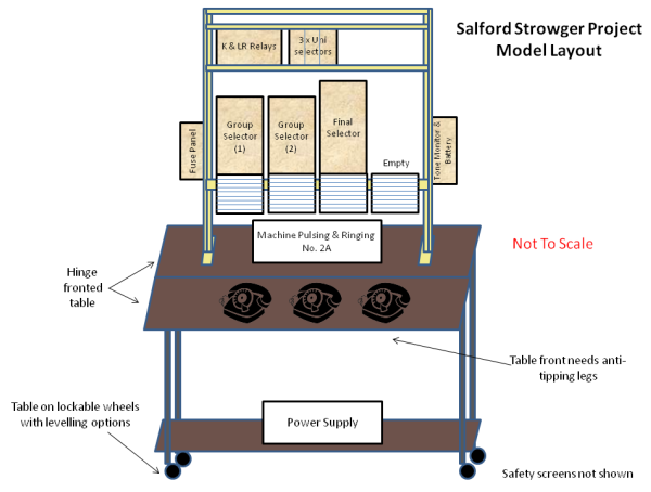
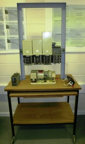
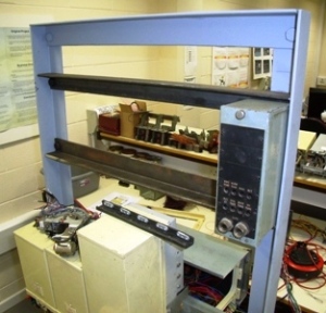
Our planned system comprised two group selectors, one final selector and three telephones. This will allow us to represent 4 number dialling, the first two numbers being handled by each of the two group selectors and the last two digits by the final selector. Each telephone will connect to the first group selector via its own uniselector and a ringing machine will provide all of the associated tones. With this arrangement we will be able to make one phone call from any telephone to either one of the remaining two. If you then try and make a call using the third telephone, appropriate busy tones will be heard. A key feature of this unit is that it must be portable and so the whole thing will be constructed on its own purpose built trolley as shown below.
Stage 1: (May 2012)
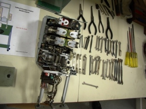
The first stage of the project was to assemble and assess the kit of Strowger parts we had collected over a number of years. This comprised a range of Strowger selectors and the associated specialist tools.
Stage 2: (May 2012)
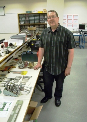
We were extremely fortunate to enlist the help of Strowger trained Openreach engineer, Andy Simmons who joined the project. Taking advantage of BT's Corporate staff volunteering scheme and supplementing this with his own personal time, Andy was able to devote a number of days to our project.
Stage 3: (June 2012)
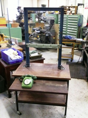
We are fortunate within the School of Computing, Science and Engineering in that we have our own dedicated mechanical workshop which is managed by Michael Clegg. Michael took responsibility for building the basic metal framework and stand on which the Strowger demo unit would be mounted.
Stage 4: (July 2012)
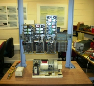
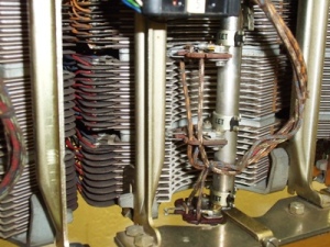
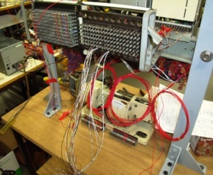
The Strowger selectors are put in place, lined up with their switch contacts and the initial wiring is made from the power supply and ringing machine.
Stage 5: (July 2012)
The final selector is tested using an engineer's butt unit and it worked as you can see from watching this video clip! In this test we are using the butt unit (out of shot) to dial two numbers. The first forces the selector to move upwards and the second to rotate to the right. When off-hook, the selector automatically resets itself. This is a 2000 type selector which means that under reset conditions, the wipers pass through the remainder of the switch bank before returning to the start position.
Stage 6: (July 2012)
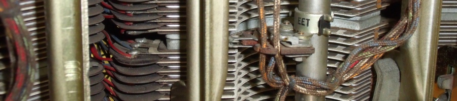
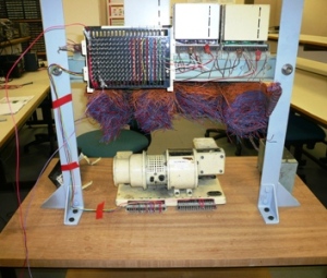
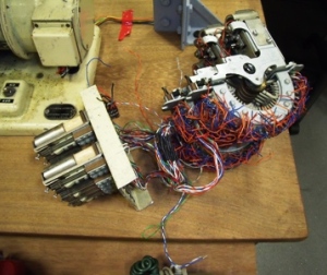
It is now time to wire up the switch banks and to test both group selectors and the final selector. With two group selectors and one final selector we have created a system that can handle 4 digit numbering. The first stage is to connect the P wires for the selectors (top part of the switch bank). These allow each selector to find the next available selector in the hierarchy. Our system is a very small scale system and so, the first group selector finds the second and the second finds the final selector. We are only permitting certain numbers to be dialled and therefore several of the levels on each group selector will be connected to a busy signal (earth). Shown here are the switch banks and the wiring which is taken onto a rear patch panel.
Now for the testing! The two group selectors and final selector are all in place. An engineer's butt unit is used to dial four digits. The first digit drives the first group selector which moves up to the bank equal to the number having been dialled. It then searches for a spare second stage group selector and the P-wire wiring allows it to stop at the first step in and select the second group selector. The next digit dialled drives this second group selector up to the level equal to the number being dialled and it then searches for a final selector, with the P-wire forcing it to stop at the first step. The third digit dialled now drives the final selector up by the number of levels dialled and then the fourth digit rotates the final selector by that amount. At this stage, having dialled all four digits, the called telephone should be connected and ringing. However, that part of the system has not yet been completed and so this test is limited to simply checking the three selectors.
Stage 7: (August 2012)
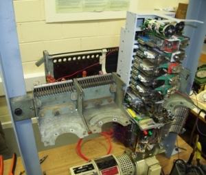
The next stage in development is to connect the uniselectors and the K and LR relays. Our system is designed to support three telephones and therefore we need three uniselectors and three sets of relays. These are shown here ready to assmebly onto the main framework.
The next step is to install the shelf onto which these uniselectors and relays will be attached. In our system this shelf will also carry a tone box as shown here.
Stage 8: (September 2012)
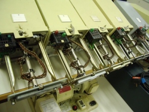
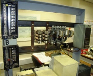
The next stage is to install the uniselectors and the K and LR relays onto the shelf supports, wire then into the system and add the fuse panel as shown below.
Once installed, the uniselectors needed to be tested. In this case, lifting a telephone off-hook should result in the uniselector searching for a free first group selector, which it does, as the video below shows!
Stage 9: (September 2012)
And so to the final complete system testing. Our Strowger demo unit is now complete with three telephones attached. In this video Andy Simmons is testing the unit by making a phone call from one telephone to another. Note how when he lifts the handset, you can hear the uniselector connected to that phone rotate until it finds a free first group selector. Then, as he dials each of the four digits, the first and then the second group selector move, followed by the final selector which responds to the last two digits dialled. At that point the call is routed through and the dialled telephone rings. When he lifts the handset of that phone, the voice circuit is connected. Finally, the system clears once he returns the handset of telephone that initiated the call to the on-hook position.
Manchester Science Festival 2012
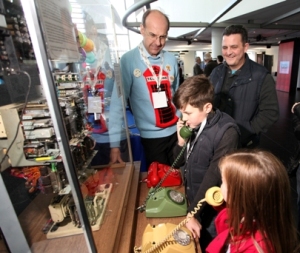
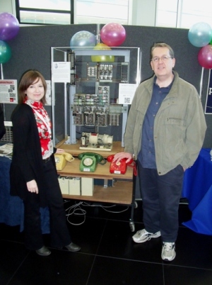
Our goal had always been to have the Strowger unit working so that it could be showcased at the Manchester Science Festival held in October 2012 which was also the centenary year of the opening of the first Strowger exchange within the UK. As part of the Science Festival we held a public telecommunications exhibition (From semaphore to smartphone) within the University of Salford's building at MediaCity Salford over the weekend of Saturday 27th and Sunday 28th October. Shown here is Andy Simmons proudly demonstrating our Strowger unit to Sian Wynn-Jones from BT Heritage.
The BT People Awards

We were absolutely delighted to hear that Andy Simmons of Openreach has won the BT People Awards (Arts and Heritage) in March 2013 for his work on our Strowger project. This award acknowledges Andy's excellent contribution to our project and thanks him for volunteering his time to our project and presents the University with a cash prize that will help us continue with our public engagement work.
BT Chairman's Award
Following on from winning a BT People's Award in March 2013 we were delighted to hear that Andy had been shortlisted for a BT Chairman's Award. On 11th June 2013 at an event held at BT Tower in London it was announced that Andy had won the BT Chairman's Award for the Arts and Heritage category. Once again, this award recognises Andy's immense commitment and contribution to the project and acknowledges the importance of ensuring we are able to preserve and continue to demonstrate some of the older tehcnology that once formed the heart of our telephone network. Click on the logo below to find out more about this award and to watch a short video profiling Andy's work.
The Project Team
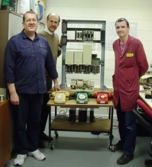
Here is our project team. On the left is Andy Simmons from Openreach with behind him, Nigel Linge from the University of Salford and on the right Michael Clegg from the mechanical workshop within the School of Computing, Science and Engineering at the University of Salford. Other team members working behing the scenes are Mike Penney, Mike Jones and Duncan Bottrill who all helped in providing materials or general assistance to the project. We are grateful to all of them!
And finally, with thanks to . . .
In the construction of our Strowger demonstration unit we are grateful for help received from the following groups and organisations:
- Openreach
- BT Archives
- The East Lancashire Railway
- The Churnet Valley Railway
- Avoncroft Museum of Historic Buildings which is part of Connected Earth
And for funding received from the College of Science and Technology Beacon Seed Awards
Follow on social media .....